Circuit Diagram Of Ir Sensor
Ir sensor : circuit diagram, types working with applications Sensor circuit infrared diagram range long Ir sensor working
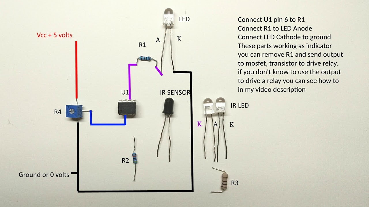
Long range infrared sensor circuit diagram - YouTube
Circuit diagram of ir sensor using 555 timer Ir sensor interfacing with microcontroller (mikro c) Arduino circuit module how2electronics
Long range infrared sensor circuit diagram
Ir sensor circuit, connection diagram, projectSensor interfacing microcontroller mikro infrared Fan speed measurement using ir sensor & arduinoIr sensor module circuit diagram test infrared breadboard make electrical implemented trying following project.
Sensor ir circuit led proximity work diagram infrared photodiode module lm358 pair 9v motion electrical object electronic using circuits icWorking of an ir sensor Diy ir sensor module circuit diagramInfrared sensors receiver circuits transmitter.
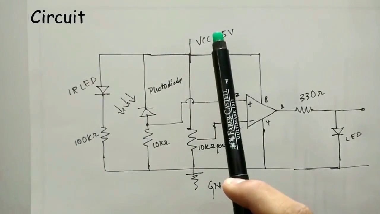
Working of an IR Sensor - YouTube

IR Sensor : Circuit Diagram, Types Working with Applications

infrared - How to test IR sensor module? - Electrical Engineering Stack

Fan Speed Measurement using IR Sensor & Arduino

DIY IR Sensor Module Circuit Diagram

IR Sensor Circuit, Connection Diagram, Project - ETechnoG
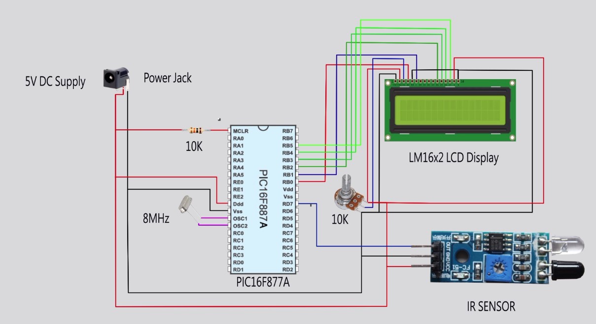
IR Sensor interfacing with microcontroller (Mikro C) - MINA TECHNOLOGY

Circuit Diagram of IR Sensor using 555 Timer - The Engineering Projects