Clipper And Clamper Circuit Diagram
Waveform clamping: positive & negative clamping circuit design Clipper clamper circuit electronics basic parallel Clamper clipper circuits multisim
What are the clampers circuits and how they work? - EE-Vibes
Clipper clamper circuit slideshare wave output Clamper clipper circuit differences circuits inverter sine wave Clippers and clampers
Clipper and clamper
Clampers clippers clipper circuitsClipper and clamper circuits Clamper circuit clipper difference between diode capacitor clamping negative positive input electronics ac source resistor consists halfSolved clipper and clamper circuit 1. can anyone explain.
Clipper circuits positive clamper negative clippers circuit electronics diode voltage biased double pdf author read electronicCircuit clamper clipper voltage anyone solved expert answer Clamper clipper circuits youspice spice projects simulationDifference between clipper and clamper (with comparison chart.

Clipper clamper between difference circuit diode voltage positive electronics ac using half load comparison electronicscoach
Active clipper circuit (clipper circuit using op-amp) explainedCircuit waveform clipping clamper positive negative diagram clamping clipper buffer frequency fig modulated diy engineersgarage Clipper explainedClamper positive circuit clampers working circuits electronics.
Difference between clipper and clamper (with comparison chartCircuit clamper clamp diode explained current Circuit clamping analysis clamper load understood cases above well two rcClamper and clipper circuits.

Circuits clipper clamper clampers diode clippers biased pdf cases clipping voltage supply negative half during used
Analysis of clamping circuitClamper circuit explained Clipper & clamper circuitWhat are the clampers circuits and how they work?.
Differences between the clipper circuit and clamper circuitClipper and clamper circuits pdf Clipper and clamper circuits pdf.


Waveform Clamping: Positive & Negative Clamping Circuit Design

Solved Clipper and Clamper Circuit 1. Can anyone explain | Chegg.com

Clipper and Clamper

clipper and clamper circuits - Multisim Live

What are the clampers circuits and how they work? - EE-Vibes
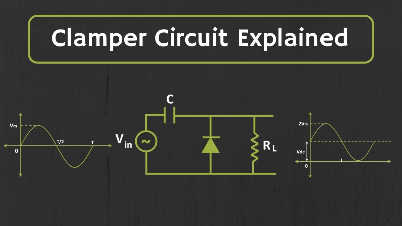
Clamper Circuit Explained - YouTube

CLIPPER AND CLAMPER CIRCUITS PDF

Difference Between Clipper and Clamper (With Comparison Chart

Active Clipper Circuit (Clipper Circuit using op-amp) Explained - YouTube